Smart Home Integration of Analog Wired Alarm System
Recently I was tasked with a project to integrate an existing built-in 1990s era analog wired home security system into a smart home automation scheme that would provide remote system status via VPN to the local network along with notifications of system changes being sent to the user's smart devices over the internet.
During my initial research, I found the following web page which seemed very promising: Total Noob Guide To Move Your Old Wired Security System to SmartThings. Even though it was a design to replace the old wired system, instead of mirroring it, I felt it could still be a good starting point. The design consisted of a SmartThings hub connected to an Arduino Board Computer incorporating a SmartThings Shield for Arduino to connect to the wired systems sensors.
Unfortunately, the SmartThings Shield was discontinued and hard to find, but I found many references to using a Raspberry Pi running "Home Assistant" as a viable alternative. This led to the initial prototype of the system being a 512MB Raspberry Pi Project Board Model B with a PiFace Digital Interface Board and, to maintain as much comparability as possible, still be able to connect to a SmartThings hub
Board Design
Each zone of the home security system consists of various numbers of contact sensors in series. When any one contact sensor is open, the voltage at the security system control panel is13.8V (nominal Vcc) and when all the contact sensors are closed, the voltage is 3.4V due to the current limiting resistor.
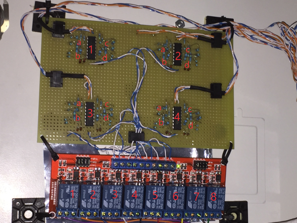
The interface board consists of voltage comparator circuits based on the LM339N, with its implicit high impedance, to minimize current drain on the existing home security system. The circuit design was based on Figure 3 on Page 2 of the spec sheet for the LM339.
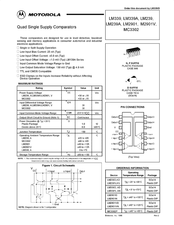

The Vref voltage divider used a 4.7K resistor for Rref and a 10K resistor for R1, which resulted in a Vref of 9.3V based on the Vcc voltage of 13.8V. The home security system had sixteen zones but, for simplicity, I reduced that to eight by combining the output of two adjacent comparators using a 1n4148 diode.
For electrical isolation, I used an 8-channel relay module to trigger the digital inputs of the PiFace board.
After testing the circuit using a protoboard, I selected a solderable PC breadboard for the actual prototype's interface board.