


Integration of Analog Wired Alarm System Part III
Configuration
Edit Home Assistant configuration file in /home/homeassistant/.homeassistant/configuration.yaml.
To use the GPIO Pins:
- binary_sensor:
platform: rpi_gpio
ports:
04: Front Doors
17: Back Doors
24: Master Bed Windows
pull_mode: UP
invert_logic: true
bouncetime : 1
To enable pushBullet notifications for changes of the GPIO Pins (repeat for each pin):
- automation:
alias: GPIO Contact 1 On
id: '1498531284301'
trigger:
platform: state
entity_id: binary_sensor.front_doors
from: 'off'
to: 'on'
action:
service: notify.pushbullet
data:
title: "Zone 1 Open"
Message: "Front Doors"
To support devices from a SmartThings hub, add the following:
- Dimmable light:
platform: mqtt
name: "Light"
state_topic: "smartthings/Light/switch"
command_topic: "smartthings/Light/switch"
brightness_state_topic: "smartthings/Light/level"
brightness_command_topic: "smartthings/Light/level"
brightness_scale: 100
payload_on: "on"
payload_off: "off"
optimistic: false
retain: true - Light switch:
platform: mqtt
name: "Light"
state_topic: "smartthings/Light/switch"
command_topic: "smartthings/Light/switch"
payload_on: "on"
payload_off: "off"
optimistic: false
retain: true - Fan:
platform: mqtt
name: "Fan"
state_topic: "smartthings/Fan/switch"
command_topic: "smartthings/Fan/switch"
speed_state_topic: "smartthings/Fan/level"
speed_command_topic: "smartthings/Fan/level"
payload_on: "on"
payload_off: "off"
payload_low_speed: "33"
payload_medium_speed: "66"
payload_high_speed: "99"
speeds:
low
medium
high
optimistic: false
retain: true
Conclusion
The Raspberry Pi hosted Home Assistant worked as expected after a few modifications. During initial testing, I found that the PiFace interface caused number of problems, ranging from excessive memory usage and timeout errors. Once the Raspberry Pi's GPIO pins were used instead of the PiFace and dtparam=spi=off,the CPU Usage generally hovered around 10% with minimal timeout errors.
There did seem to be one last minor issue, either related to the poor performance of the Raspberry Pi chosen for the prototype or due to a design flaw in Home Assistant. The problem arose when a high communications load was placed on the Raspberry Pi either through the sensor platform: speedtest, or through the sensor platform: yr, which retrieves the weather forecast from the Norwegian Meteorological Institute and the NRK. The temporary solution was to simply disable the weather forecast and to only to use speedtest once per day.
Integration of Analog Wired Alarm System Part II
Software Design
As their website states: Home Assistant is an open-source home automation platform running on Python 3. Track and control all devices at home and automate control. Perfect to run on a Raspberry Pi.
Because I was going to run my Raspberry Pi headless, I installed PuTTY on my Windows 10 machine for SSH.
One of the first things I noticed was that my keyboard number pad didn’t work in PuTTY. It turns out that in the Raspberry Pi the default keyboard is “gb” and I needed to change it to “us”. This was done by editing the /etc/default/keyboard file to change XBBLAYOUT=”us”.
I also found the right mouse button, which is used for pasting text, to be overly sensitive. I changed the PuTTY configuration for the “Action of mouse buttons:” to “Windows…” from “Compromise…” so that a right mouse click now displays a context menu instead of just pasting what’s in the buffer.
There a currently three ways to install Home Assistant on a Raspberry Pi: from a complete turnkey installation, Hass.io to an All-in-One installer on top of Raspbian to a customized operating system, HASSbian.
I decided to go with HASSbian because it still allowed some access to the OS, and then used the standard instructions for a wired network. HASSbian provided support for most of what I needed but not SmartThings which required additional steps for installation and configuration. Also, since Home Assistant is written Python 3, you have access to all the source files at /srv/homeassistant/lib/python3.4/site-packages/homeassistant in case you need to edit them.
These are the steps I did to update and configure HASSbian after the initial installation. Steps nine and ten are for changing the database that is used for the recorder to MySQL, which has much better performance. Steps nine through fourteen are for adding SmartThings support.
- Change the password of the default user pi from ‘raspberry’
- Passwd
- Passwd
- Change swappiness to 10 in 98-rpi.conf since swap on SD Card
- Sudo nano /etc/sysctl.d/ 98-rpi.conf
- Add
- vm.swappiness = 10
- vm.swappiness = 10
- Edit config.txt to enable PiFace (platform: rpi_pfio)
- Sudo nano /boot/config.txt
- Uncomment
- dtparam=spi=on
- dtparam=spi=on
- Uncomment
- Sudo nano /boot/config.txt
- Install raspi-gpio for checking rpi_gpio pins
- sudo apt-get install raspi-gpio
- sudo raspi-gpio get xx (xx - GPIO pin)
- Edit Home Assistant configuration file to use PushBullet
- cd /home/homeassistant/.homeassistant
- sudo nano configuration.yaml
- Add
notify:
platform: pushbullet
api_key: 'YOUR_KEY'
name: pushbullet
- Add
- Use hasbian-config to install additional packages
- sudo hassbian-config install mosquitto
(MQTT broker) - sudo hassbian-config install samba
(Adds home share for the raspberry Pi)
- sudo hassbian-config install mosquitto
- Edit smb.conf to add additional shares
- sudo nano /etc/samba/smb.conf
- Add
[home]
path = /home/pi
writeable = yes
guest ok = yes
create mask = 0644
directory mask = 0755
force user = pi
- Add
- sudo systemctl restart smbd.service
- sudo nano /etc/samba/smb.conf
- With samba, you can use Notepad++ to edit configuration YAML files on PC
- Install MySQL and MySQL Client from switched instructions
- sudo apt-get install libmysqlclient-dev
Or if using the MariaDB: - sudo apt-get install libmariadbclient-dev
- sudo apt-get install python-dev python3-dev
- sudo apt-get install mysql-server
(Create root password when prompted) - sudo mysql -u root -p
(Enter root password) - CREATE DATABASE hass_db;
- CREATE USER 'hassuser'@'localhost' IDENTIFIED BY 'XXX';
(XXX is your password) - GRANT ALL PRIVILEGES ON *.* TO 'hassuser'@'localhost';
- FLUSH PRIVILEGES;
- QUIT;
- sudo su -s /bin/bash homeassistant
(Enter the virtual environment) - source /srv/homeassistant/bin/activate
- pip3 install --upgrade mysqlclient
- exit
- sudo apt-get install libmysqlclient-dev
- Edit Home Assistant configuration file to use MySQL
- cd /home/homeassistant/.homeassistant
- sudo nano configuration.yaml
- Add
recorder:
db_url: mysql://hassuser:XXX@127.0.0.1/hass_db?charset=utf8(XXX is your password)
- Add
- Install Docker from their repository per TaperCrimp instructions
- curl -sSL https://get.docker.com | sh
- curl -sSL https://get.docker.com | sh
- Rebuild the Docker instance of smartthings-mqtt-bridge (all one line)
- sudo docker build -t smartthings-mqtt-bridge -f Dockerfile-rpi \
https://github.com/stjohnjohnson/\
smartthings-mqtt-bridge.git - sudo docker run --restart=always -d --name="mqtt-bridge" -v \
/opt/mqtt-bridge:/config -p 8080:8080 smartthings-mqtt-bridge
- sudo docker build -t smartthings-mqtt-bridge -f Dockerfile-rpi \
- Edit mosquito.conf to allow anonymous connections
- sudo nano /etc/mosquito/mosquito.conf
- Add
- allow_anonymous true
- allow_anonymous true
- Add
- sudo nano /etc/mosquito/mosquito.conf
- Edit the MQTT configuration file
- sudo nano /opt/mqtt-bridge/config.yml
- Add
mqtt:
host: mqtt://IP Address of Pi
preface: smartthings
port: 8080
- Add
- sudo nano /opt/mqtt-bridge/config.yml
- Edit Home Assistant configuration file to use MQTT
- cd /home/homeassistant/.homeassistant
- sudo nano configuration.yaml
- Add
mqtt:
broker: localhost
discovery: true
discovery_prefix: smartthings
- Add
- Edit rc.local to auto start mqtt-bridge
- sudo nano /etc/rc.local
- Add
- sudo docker restart mqtt-bridge
- sudo docker restart mqtt-bridge
- Add
- sudo nano /etc/rc.local
- Update HASSbian
- sudo apt-get update
- sudo apt-get -y upgrade
- Update Home Assistant
- sudo systemctl stop This email address is being protected from spambots. You need JavaScript enabled to view it.
- sudo su -s /bin/bash homeassistant
- source /srv/homeassistant/bin/activate
- pip3 install --upgrade homeassistant
- exit
- sudo systemctl start This email address is being protected from spambots. You need JavaScript enabled to view it.
For SmartThings to communicate to the Home Assistant running on the Raspberry Pi, support needs to be added for the MQTT Bridge.These steps are based on stjohnjohnson instructions for smartthings-mqtt-bridge
- Install Device Handler using SmartThings web site
- My Device Handlers -> Create New Device Handler -> From Code
- Then click Publish -> For Me
- My Device Handlers -> Create New Device Handler -> From Code
- Add the “MQTT Device” to the local SmartTHINGS hub
- My Locations ->Home -> My Devices -> New Device
Name: MQTT Bridge
Device Network ID: MAC Address of Pi
Type: MQTT Bridge
Version: Self-Published
Location: Home
- My Locations ->Home -> My Devices -> New Device
- Configure the “MQTT Device” in the local SmartThings hub
- My Devices -> MQTT Bridge -> Preferences (edit)
MQTT Bridge IP Address: IP Address of Pi
MQTT Bridge Port: 8080
MQTT Bridge MAC Address: MAC Address of Pi
- My Devices -> MQTT Bridge -> Preferences (edit)
- Add the MQTT Bridge Smart App code to the local SmartTHINGS hub
- My SmartApps -> New SmartApp -> From Code
- My SmartApps -> New SmartApp -> From Code
- Add the MQTT Bridge Smart App to the SmartApps using the iOS App
- Automation -> SmartApps -> Add a SmartApp-> My Apps
- Automation -> SmartApps -> Add a SmartApp-> My Apps
- Add devices to the MQTT Smart App using the iOS App
- Automation -> SmartApps -> MQTT Bridge
Projects
Example Projects:
- GARS
- GTRI RMS Server
- Weather Balloon with Real-time Tracking
- Smart Home Integration of Analog Wired Alarm System
Integration of Analog Wired Alarm System Part I
Smart Home Integration of Analog Wired Alarm System
Recently I was tasked with a project to integrate an existing built-in 1990s era analog wired home security system into a smart home automation scheme that would provide remote system status via VPN to the local network along with notifications of system changes being sent to the user's smart devices over the internet.
During my initial research, I found the following web page which seemed very promising: Total Noob Guide To Move Your Old Wired Security System to SmartThings. Even though it was a design to replace the old wired system, instead of mirroring it, I felt it could still be a good starting point. The design consisted of a SmartThings hub connected to an Arduino Board Computer incorporating a SmartThings Shield for Arduino to connect to the wired systems sensors.
Unfortunately, the SmartThings Shield was discontinued and hard to find, but I found many references to using a Raspberry Pi running "Home Assistant" as a viable alternative. This led to the initial prototype of the system being a 512MB Raspberry Pi Project Board Model B with a PiFace Digital Interface Board and, to maintain as much comparability as possible, still be able to connect to a SmartThings hub
Board Design
Each zone of the home security system consists of various numbers of contact sensors in series. When any one contact sensor is open, the voltage at the security system control panel is13.8V (nominal Vcc) and when all the contact sensors are closed, the voltage is 3.4V due to the current limiting resistor.
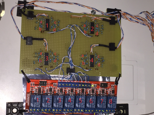
The interface board consists of voltage comparator circuits based on the LM339N, with its implicit high impedance, to minimize current drain on the existing home security system. The circuit design was based on Figure 3 on Page 2 of the spec sheet for the LM339.


The Vref voltage divider used a 4.7K resistor for Rref and a 10K resistor for R1, which resulted in a Vref of 9.3V based on the Vcc voltage of 13.8V. The home security system had sixteen zones but, for simplicity, I reduced that to eight by combining the output of two adjacent comparators using a 1n4148 diode.
For electrical isolation, I used an 8-channel relay module to trigger the digital inputs of the PiFace board.
After testing the circuit using a protoboard, I selected a solderable PC breadboard for the actual prototype's interface board.
Weather Balloon with Real-time Tracking
Weather Balloon with Real-time Tracking and High-Altitude Image Capture.
While primarily a software company, occasionally we get the opportunity to work on the electronic side of a project and sometimes even get the chance to do a little fabrication. Such was the case for the Weather Balloon with Real-time Tracking project that was done for a local high school.
Building and launching the balloon
Building the weather balloon took a fair amount of effort, as it was built from scratch without a kit. We chose to build the balloon using an insulated Styrofoam box with a small window cut in it for the camera. Due to FAA regulations, we also had to attach a radar reflector which was made from cardboard and coated in aluminum foil. The entire balloon was built such that it would be easily broken apart if hit by aircraft, per FAA regulations.
On the internals side, we installed a 10 watt APRS radio beacon made by Byonics, which was attached to an array of 8 AAA lithium batteries, due to its high current pull while transmitting. The GPS module used was a special model acquired from Adafruit Industries that allowed usage over 60000 feet, as long as the speed was below 1000 knots (a DOD ballistic missiles restriction, AKA COCOM Limits, prevents GPS from working if both of these conditions are met, although many manufacturers switch on one or the other). The serial output from the GPS was split between the APRS beacon and a specially modified Raspberry Pi model A, that we installed a buck–boost converter on, in order to improve efficiency of the power supply and to work with its individual lithium ion battery pack.
The Raspberry Pi, programmed in Python, was hooked to a camera module over CSI (Camera Serial Interface) and mounted with a fish-eye lens to the window in the balloon. We used a 3D printer to make a number of different parts in order to mount the Raspberry Pi, the camera and the lens. The Pi was also hooked up to a dangling temperature probe and a cutoff switch, allowing it to be safely shut down when recovered. The camera was programmed to take approximately one picture per minute and log the GPS location and outside temperature to the file as it flew.
Map of balloon's flight
The balloons flight was tracked by using the ham radio system called APRS (Automatic Packet Reporting System), and a website called aprs.fi, which takes information fed to a network of receivers and then plots the location information on a google earth map. You can see the balloons trajectory as well as altitude in the image below. The balloon flew much farther than was originally intended, but due to over spec’ing of the batteries, the transmitter continued to function for around 4 hours.

Images from the flight of the balloon
The balloon flew much higher and longer than initially intended partially due to the better-than-expected quality of the balloon and to the fact that the balloon got caught in the jet stream at one point, causing it to move at over 100 mph. Once we recovered the balloon, the pictures were retrieved from the internal camera. You can see when the balloon pops, at roughly 2:40 minutes, as the camera turns sideways as the balloon enters free fall. Due to the thin atmosphere at the burst point (94,000 feet), the parachute does not deploy until much later, when there is enough air to allow it to open and glide down to the ground.
Recovering the balloon
Recovering the balloon posed a challenge as the battery died due to its long flight, roughly a mile above the ground. However, by extrapolating from the balloon's last known position, its flight path and the weather conditions, we were able to pinpoint its landing location (33.793659, -105.179001, the only square of public land in 400 sq. miles of ranches!) and recover the balloon (only an 8-9 hour round trip!). The balloon remained air and water tight through its landing and all components were functional, short of half of the antenna which pulled away on landing from its strain relief.


